- 您现在的位置:买卖IC网 > Sheet目录341 > MAX6948BGWA+T (Maxim Integrated)IC LED DVR PWM GPIO 25WLP
�� �
�
�MAX6948B�
�High-Efficiency� PWM� LED� Driver� with� Boost�
�Converter� and� Five� Constant-Current� GPIO� Ports�
�Operation� with� Multiple� Masters�
�When� the� MAX6948B� is� operated� on� a� 2-wire� interface�
�with� multiple� masters,� a� master� reading� the� MAX6948B�
�uses� a� repeated� start� between� the� write� that� sets� the�
�MAX6948B’s� address� pointer,� and� the� read(s)� that� takes�
�the� data� from� the� location(s).� This� is� because� it� is� pos-�
�sible� for� master� 2� to� take� over� the� bus� after� master� 1� has�
�set� up� the� MAX6948B’s� address� pointer� but� before� mas-�
�ter� 1� has� read� the� data.� If� master� 2� subsequently� resets�
�the� MAX6948B’s� address� pointer,� master� 1’s� read� can�
�be� from� an� unexpected� location.�
�Command� Address� Autoincrementing�
�Address� autoincrementing� allows� the� MAX6948B� to� be�
�configured� with� fewer� transmissions� by� minimizing� the�
�number� of� times� the� command� address� needs� to� be�
�sent.� The� command� address� stored� in� the� MAX6948B�
�generally� increments� after� each� data� byte� is� written� or�
�read� (Table� 1).� Autoincrement� only� works� when� doing� a�
�burst� read� or� write.�
�Applications� Information�
�Inductor� Selection�
�The� MAX6948B� is� optimized� for� a� 10� F� H� inductor,�
�although� larger� or� smaller� inductors� can� be� used.� Using�
�a� smaller� inductor� results� in� discontinuous-current-mode�
�operation� over� a� larger� range� of� output� power,� whereas�
�use� of� a� larger� inductor� results� in� continuous� conduction�
�for� most� of� the� operating� range.�
�To� prevent� core� saturation,� ensure� that� the� inductor’s�
�saturation� current� rating� exceeds� the� peak� inductor� cur-�
�rent� for� the� application.� For� larger� inductor� values� and�
�continuous� conduction� operation,� calculate� the� worst-�
�case� peak� inductor� current� with� the� following� formula:�
�V� OUT� ×� I� OUT(MAX)� V� IN(MIN)� ×� 0.5� μ� s�
�I� PEAK�
�=� +�
�0.9� � V� IN(MAX)� 2� � L�
�Otherwise,� for� small� values� of� L� in� discontinuous� conduc-�
�tion� operation,� I� PEAK� is� 860mA� (typ).� Table� 14� provides� a�
�list� of� recommended� inductors.�
�Capacitor� Selection�
�The� typical� input� capacitor� value� is� 2.2� F� F� and� the� typical�
�output� capacitor� is� 0.22� F� F.� Higher� value� capacitors� can�
�reduce� input� and� output� ripple,� but� at� the� expense� of� size�
�and� higher� cost.� For� best� operation,� use� ceramic� X5R� or�
�X7R� dielectric� capacitors.� Generally,� ceramic� capacitors�
�with� smaller� case� sizes� have� poorer� DC� bias� character-�
�istics� than� larger� case� sizes� for� a� certain� capacitance�
�value.� Select� the� capacitor� that� yields� the� best� trade-off�
�between� case� size� and� DC� bias� characteristics.�
�Diode� Selection�
�The� high� switching� frequency� of� the� MAX6948B� demands�
�a� high-speed� rectification� diode� for� optimum� efficiency.�
�A� Schottky� diode� is� recommended� due� to� its� fast� recov-�
�ery� time� and� low� forward-voltage� drop.� Ensure� that� the�
�diode’s� average� and� peak� current� rating� exceeds� the�
�average� output� current� and� peak� inductor� current.� In�
�addition,� the� diode’s� reverse-breakdown� voltage� must�
�exceed� V� OUT� .�
�Compensation� Network� Selection�
�The� step-up� converter� uses� an� external� compensation�
�network� from� COMP� to� GND� to� ensure� stability.� For� 5� or� 6�
�WLEDs,� choose� C� COMP� =� C� OUT� /10� for� optimal� transient�
�response.�
�Port� Input� and� I� 2� C� Interface� Logic� Voltages�
�The� MAX6948B� I� 2� C� supply� (V� DD� )� accepts� voltages�
�from� 1.7V� up� to� the� boost-converter� input� (V+).� V� DD�
�determines� the� I� 2� C� interface� (SDA,� SCL),� I� 2� C� slave-�
�address� select� input� (AD0),� and� reset� input� (� RST� )� logic�
�voltages.� The� five� I/O� ports� P0–P4� are� overvoltage� pro-�
�tected� to� 5.5V� independent� of� V� DD� or� V+.� This� allows� the�
�MAX6948B� to� operate� from� one� supply� voltage,� such� as�
�3.3V,� while� driving� some� of� the� five� I/Os� as� inputs� from� a�
�different� logic� level,� such� as� 5V.�
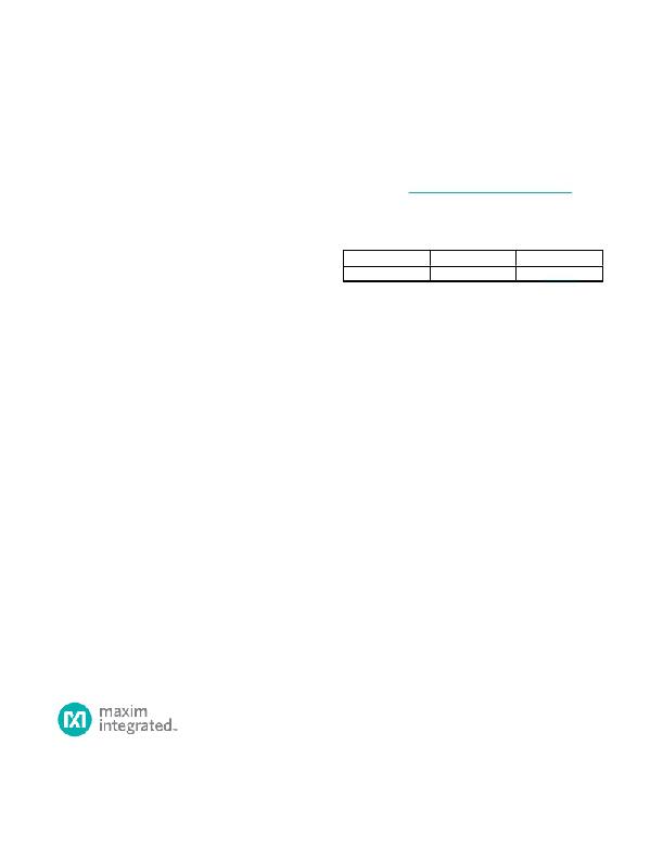
�Table� 14.� Recommended� Inductors�
�VENDOR� PART� NUMBER�
�TOKO� 1069AS-220M�
�TOKO� 1098AS-100M�
�L�
�(μH)�
�22�
�10�
�DCR�
�(m� ω� )�
�570�
�290�
�I� SAT�
�(A)�
�0.47�
�0.75�
�CASE� SIZE�
�(mm)�
�3� x� 3� x� 1.8�
�2.8� x� 3� x� 1.2�
�Maxim� Integrated�
�25�
�发布紧急采购,3分钟左右您将得到回复。
相关PDF资料
MAX6964ATG+T
IC LED DRIVER LINEAR 24-TQFN
MAX6965ATE+T
IC LED DRIVER LINEAR 16-TQFN
MAX6967ATE+
IC LED DRIVER LINEAR 16-TQFN
MAX6968AAE+
IC LED DRIVER LINEAR 16-SSOP
MAX6970AUE+
IC LED DRIVER LINEAR 16-TSSOP
MAX6971AUG+T
IC LED DRIVER LINEAR 24-TSSOP
MAX6974ATL+
IC LED DRIVER LINEAR 40-TQFN
MAX6977AAE+
IC LED DRIVER LINEAR 16-SSOP
相关代理商/技术参数
MAX694C/D
功能描述:监控电路 RoHS:否 制造商:STMicroelectronics 监测电压数: 监测电压: 欠电压阈值: 过电压阈值: 输出类型:Active Low, Open Drain 人工复位:Resettable 监视器:No Watchdog 电池备用开关:No Backup 上电复位延迟(典型值):10 s 电源电压-最大:5.5 V 最大工作温度:+ 85 C 安装风格:SMD/SMT 封装 / 箱体:UDFN-6 封装:Reel
MAX694CPA
功能描述:监控电路 RoHS:否 制造商:STMicroelectronics 监测电压数: 监测电压: 欠电压阈值: 过电压阈值: 输出类型:Active Low, Open Drain 人工复位:Resettable 监视器:No Watchdog 电池备用开关:No Backup 上电复位延迟(典型值):10 s 电源电压-最大:5.5 V 最大工作温度:+ 85 C 安装风格:SMD/SMT 封装 / 箱体:UDFN-6 封装:Reel
MAX694CPA+
功能描述:监控电路 MPU Supervisor RoHS:否 制造商:STMicroelectronics 监测电压数: 监测电压: 欠电压阈值: 过电压阈值: 输出类型:Active Low, Open Drain 人工复位:Resettable 监视器:No Watchdog 电池备用开关:No Backup 上电复位延迟(典型值):10 s 电源电压-最大:5.5 V 最大工作温度:+ 85 C 安装风格:SMD/SMT 封装 / 箱体:UDFN-6 封装:Reel
MAX694EJA
功能描述:监控电路 RoHS:否 制造商:STMicroelectronics 监测电压数: 监测电压: 欠电压阈值: 过电压阈值: 输出类型:Active Low, Open Drain 人工复位:Resettable 监视器:No Watchdog 电池备用开关:No Backup 上电复位延迟(典型值):10 s 电源电压-最大:5.5 V 最大工作温度:+ 85 C 安装风格:SMD/SMT 封装 / 箱体:UDFN-6 封装:Reel
MAX694EPA
功能描述:监控电路 RoHS:否 制造商:STMicroelectronics 监测电压数: 监测电压: 欠电压阈值: 过电压阈值: 输出类型:Active Low, Open Drain 人工复位:Resettable 监视器:No Watchdog 电池备用开关:No Backup 上电复位延迟(典型值):10 s 电源电压-最大:5.5 V 最大工作温度:+ 85 C 安装风格:SMD/SMT 封装 / 箱体:UDFN-6 封装:Reel
MAX694EPA+
功能描述:监控电路 MPU Supervisor RoHS:否 制造商:STMicroelectronics 监测电压数: 监测电压: 欠电压阈值: 过电压阈值: 输出类型:Active Low, Open Drain 人工复位:Resettable 监视器:No Watchdog 电池备用开关:No Backup 上电复位延迟(典型值):10 s 电源电压-最大:5.5 V 最大工作温度:+ 85 C 安装风格:SMD/SMT 封装 / 箱体:UDFN-6 封装:Reel
MAX694MJA
功能描述:监控电路 RoHS:否 制造商:STMicroelectronics 监测电压数: 监测电压: 欠电压阈值: 过电压阈值: 输出类型:Active Low, Open Drain 人工复位:Resettable 监视器:No Watchdog 电池备用开关:No Backup 上电复位延迟(典型值):10 s 电源电压-最大:5.5 V 最大工作温度:+ 85 C 安装风格:SMD/SMT 封装 / 箱体:UDFN-6 封装:Reel
MAX694MJA/883B
功能描述:监控电路 MPU Supervisor RoHS:否 制造商:STMicroelectronics 监测电压数: 监测电压: 欠电压阈值: 过电压阈值: 输出类型:Active Low, Open Drain 人工复位:Resettable 监视器:No Watchdog 电池备用开关:No Backup 上电复位延迟(典型值):10 s 电源电压-最大:5.5 V 最大工作温度:+ 85 C 安装风格:SMD/SMT 封装 / 箱体:UDFN-6 封装:Reel